

- Home
- Request for Quote
- Products
- Variable Frequency Drive Systems and Controls
- AC Variable Frequency Drives
- ABB ACS150 Component Drives :: Overview
- ABB ACS150 Component Drives :: Technical Specifications
- ABB ACS150 Component Drives :: Ratings, Types, Voltages and Construction – Prices
- ABB ACS150 Component Drives :: Dimensions, Weight and Noise
- ABB ACS150 Component Drives :: Interface and Options (prices)
- ABB ACS150 Component Drives :: Technical Data
- ABB ACS150 Component Drives :: Control Connections
- ABB ACS350 General Machinery Drives :: Overview
- ABB ACS350 General Machinery Drives :: Technical Specifications
- ABB ACS350 General Machinery Drives :: Ratings, Types, Voltages and Construction
- ABB ACS350 General Machinery Drives :: Dimensions, Weight and Noise
- ABB ACS350 General Machinery Drives :: Interface and Options (prices)
- ABB ACS350 General Machinery Drives :: Technical Data
- ABB ACS350 General Machinery Drives :: Control Connections
- ABB ACS550 AC Variable Frequency Drive :: Overview
- ABB ACS550 AC Variable Frequency Drive :: Hardware Description
- ABB ACS550 AC Variable Frequency Drive :: Standard Features and Options
- ABB ACS550 AC Variable Frequency Drive :: Specifications
- ABB ACS550 AC Variable Frequency Drive :: 230V Ratings (pricing)
- ABB ACS550 AC Variable Frequency Drive :: 380V Ratings (pricing)
- ABB ACS550 AC Variable Frequency Drive :: 480V Ratings (pricing)
- ABB ACS550 AC Variable Frequency Drive :: Dimensions: ACS550 NEMA 1 R1 through R6 Frame Size
- ABB ACS550 AC Variable Frequency Drive :: Dimensions: ACS550 NEMA 12 R1 through R6 Frame Size
- ABB ACS550 AC Variable Frequency Drive :: Dimensions: ACS550-02 NEMA 1 R7 Frame Size
- ABB ACS550 AC Variable Frequency Drive :: Dimensions: ACS550-02 NEMA 1 R8 Frame Size
- ABB ACS550 AC Variable Frequency Drive :: Dimensions: ACS550-U2 NEMA 1 R7 & R8 Frame Size
- ABB ACS 600 Adjustable Speed AC Drives
- ABB ACS800 AC Variable Frequency Drive :: Overview
- ABB ACS800 AC Variable Frequency Drive :: Standard Features / Available Options and Software
- ABB ACS800 AC Variable Frequency Drive :: Specifications
- ABB ACS800 AC Variable Frequency Drive :: Basic Type Code Information
- ABB ACS800 AC Variable Frequency Drive :: 230V Ratings (pricing)
- ABB ACS800 AC Variable Frequency Drive :: 380V Ratings (pricing)
- ABB ACS800 AC Variable Frequency Drive :: 460V Ratings (pricing)
- ABB ACS800 AC Variable Frequency Drive :: ACS 800-U2 NEMA 1 R7 & R8 Frame Size and ACS 800-02+C111 IP21 (NEMA 1) R7 & R8 Frame Size
- ABB ACS800 AC Variable Frequency Drive :: ACS 800 NEMA 1/12 R2 through R6 Frame Size
- ABB ACS800 AC Variable Frequency Drive :: ACS 800-02 NEMA 1 R7 & R8 Frame Size
- ABB ACS800 AC Variable Frequency Drive :: ACS 800-U4 Module R7 Frame Size
- ABB ACS800 AC Variable Frequency Drive :: ACS 800-U4 Module R8 Frame Size
- ABB ACS880 Industrial Low Voltage AC Drives
- ABB ACS880 AC Drives – Technical Data
- Wall-mounted single drives, ACS880-01
- ABB ACS880 Ratings, types and voltages
- ABB ACS880 AC Drives – Dimensions & Connectivity
- ABB ACS880 AC Drives – Standard Software
- ABB ACS880 AC Drives – Intuitive Human-Machine Interface
- ABB ACS880 AC Drives – Integrated Safety
- ABB ACS880 AC Drives – Flexible Connectivity
- Input/output Modules, Speed Feedback Interfaces & Communication Modules
- ABB Softstarters, Type SSM, Medium Voltage, 2300-13,800V :: Description
- ABB Type SSM Softstarters – Medium Voltage, 2300-13,800V :: General Information
- ABB Type SSM Soft Starters – Medium Voltage, 2300 – 13,800V :: Catalog Numbers
- ABB Soft Starters, Type SSM – Medium Voltage, 2300-13,800V :: Technical Data
- ABB Softstarters, Type SSM, Medium Voltage, 2300-13,800V :: Approx. Dimensions
- Yaskawa AC Drives
- AuCom Soft Starters
- Emerson Industrial Automation (Control Techniques and Saftronics) AC Drives
- Control Techniques – Commander SE AC Drive
- Control Techniques – Commander SK AC Drive
- Commander SK :: Features
- Commander SK :: Terminal Diagram and Description
- Commander SK :: Specifications and Dimensions
- Commander SK – Options :: Overview
- Commander SK – Options :: Configuration and Programming
- Commander SK :: Operator Interface
- Commander SK :: Power Accessories
- Commander SK :: Environmental Protection and Cable Management
- Commander SK :: Input / Output
- Commander SK :: Communication
- Commander SK :: Programming Software
- Control Techniques – Commander SX AC Drive
- Commander SX :: Features, Ratings, Prices and Ordering
- Commander SX :: Terminal Diagram and Description
- Commander SX:: Specifications and Dimensions
- Commander SX :: Options – Overview / Drive Configuration and Programming
- Commander SX :: Communication / Operator Interface
- Commander SX :: Power Accessories
- Commander SX :: Input/Output and Communication
- Control Techniques – Unidrive SP AC Drive
- Unidrive SP :: Features
- Unidrive SP :: Ratings, Prices & Ordering – Wall Mount
- Unidrive SP :: Ratings, Prices & Ordering – Free Standing Cubicle
- Unidrive SP :: Unidrive SP Regen Mode
- Unidrive SP :: Terminal Diagram and Description
- Unidrive SP :: Specifications and Dimensions
- Unidrive SP :: Options – Overview
- Unidrive SP :: Operator Interface
- Unidrive SP :: Power Accessories
- Unidrive SP :: Option & Feedback Modules
- Unidrive SP :: Option Input / Output Modules
- Unidrive SP :: Option Application / Programming Modules
- Unidrive SP :: Option Communication Modules
- Unidrive SP :: Drive Configuration and Programming
- Unidrive SP :: Application Programming Software
- Unidrive SP :: Pre-packaged Solutions
- Saftronics GP10 AC Drives
- Saftronics GP10 – Pricing, Dimensions & Weights
- Saftronics GP10 – Optional DC Link Reactors
- Saftronics GP10 – Options & Accessories
- Saftronics GP10 – Palm Pilot Saflink Kit
- Saftronics GP10 – SR10 Radio Modem Kit
- Saftronics GP10 – Relay Output Card
- Saftronics GP10 – Digital I/O Interface Card
- Saftronics GP10 – Analog I/O Interface Card
- Saftronics GP10 – SF-10 Ethernet Module
- Saftronics GP10 – Interface Option Card
- Saftronics GP10 – Under Torque Detection Option
- Saftronics GP10 – 24 VDC or 24/120 VAC Interface
- Saftronics GP10 – Air Pressure Sensor + V/I Converter Output Card
- Saftronics GP10 – HMI Pump Controller
- Saftronics GP10 – SDBU – Dynamic Brake Module
- Saftronics GP10 – 208-230V Dynamic Brake Packages
- Saftronics GP10 – 460V Dynamic Brake Packages
- Saftronics GP10 – Ratings Efficiency & Watts Loss
- Saftronics GP10 – Standard Specifications
- Saftronics GP10 – Basic Connection Diagram
- Saftronics GP10 – Basic Connection Diagram to PLC
- Saftronics GP10 – Basic Connection Diagram (Europe)
- Saftronics GP10 – Basic Connection to PLC (Europe)
- Saftronics S10 AC Drives
- Saftronics S10 – Options and Accessories
- Saftronics S10 – Standard Specifications
- Saftronics S10 – Dimensions
- Saftronics S10 – Dimensions – Part Number: S102002 – S102003 & S104001 – S104003
- Saftronics S10 – Dimensions – Part Number: S102F25 – S102001
- Saftronics S10 – Dimensions — Part Number: S102F25 – S102001 no Operators
- Saftronics S10 – Dimensions – Part Number: S102002-2003 & S104001-4003
- Saftronics S10 – Basic Wiring Diagram
- Saftronics CV10 AC Drives
- Saftronics CV10 – Part Numbers, Dimensions & Weights
- Saftronics CV10 – LED Keypad with Speed Pot
- Saftronics CV10 – LCD Keypad (supports 5 Languages)
- Saftronics CV10 – Keypad Extension Cable
- Saftronics CV10 – Communication Option Cards
- Saftronics CV10 – Bi-Polar Speed Reference Option Card
- Saftronics CV10 – Standard Specifications
- Saftronics CV10 – Ratings Efficiency and Watts Loss
- Saftronics CV10 – Dimensions Frame 1 – IP20 (Open Chassis)
- Saftronics CV10 – Dimensions Frame 1 – NEMA 1
- Saftronics CV10 – Dimensions Frame 2 – IP20 (Open Chassis)
- Saftronics CV10 – Dimensions Frame 2 – NEMA 1
- Saftronics CV10 – Dimensions Frame 3 – IP20 (Open Chassis)
- Saftronics CV10 – Dimensions Frame 3 – NEMA 1
- Saftronics CV10 – Basic Wiring Diagram
- Saftronics VG10 AC Drive
- Saftronics VG10 – Pricing, Dimensions & Weights
- Saftronics VG10 – Optional DC Link Reactors
- Saftronics VG10 – Options and Accessories
- Saftronics VG10 – Palm Pilot Saflink Kit
- Saftronics VG10 – Relay Output Card
- Saftronics VG10 – SR10 Radio Modem Kit
- Saftronics VG10 – Digital I/O Interface Card
- Saftronics VG10 – Analog I/O Interface Card
- Saftronics VG10 – SF-10 Ethernet Module
- Saftronics VG10 – PGX Encoder Feedback Card
- Saftronics VG10 – Encoder + Analog Output Card
- Saftronics VG10 – PG Feedback Card SOPCG11SPG
- Saftronics VG10 – PG Feedback Card SOPCG11SPG2
- Saftronics VG10 – Synchronized Operation Card
- Saftronics VG10 – 24 VDC or 24/120 VAC Interface Card Kit
- Saftronics VG10 – Air Pressure Sensor + V/I Converter Output Card
- Saftronics VG10 – SDBU – Dynamic Brake Module
- Saftronics VG10 – 208-230V Dynamic Brake Packages
- Saftronics VG10 – 460V Dynamic Brake Packages
- Saftronics VG10 – Ratings Efficiency and Watts Loss
- Saftronics VG10 – Standard Specifications
- Saftronics VG10 – DC Link Reactor 100 HP and Above
- Saftronics VG10 – Basic Connection Diagram (Sink Logic, Mainly America)
- Saftronics VG10 – Basic Connection Diagram to PLC (Sink Logic, Mainly America)
- Saftronics VG10 – Basic Connection Diagram (Source Logic, Mainly Europe)
- Saftronics VG10 – Basic Connection Diagram to PLC (Source Logic, Mainly Europe)
- Saftronics PC10 (Obsolete) AC Drives
- Saftronics PC10 – Options & Accessories
- Saftronics PC10 – SF-10 Ethernet Module Kit
- Saftronics PC10 – 24 VDC or 24/120 VAC Input + Relay Option Card
- Saftronics PC10 – 24 VDC or 24/120 VAC Interface Card Kit (PC10, GP10, or VG10 Inverter)
- Saftronics PC10 – Relay Output Card
- Saftronics PC10 – HMI Pump Controller
- Saftronics PC10 – PC10 120 VAC Option Card
- Saftronics PC10 – Palm Pilot Saflink Kit
- Saftronics PC10 – Dynamic Braking
- Saftronics PC10 – Drive Ratings Efficiency and Watts Loss
- Saftronics PC10 – Standard Specifications
- Saftronics PC10 – Part Number: PC102F12-9, PC102F25-9, PC102F50-9 & PC102001-9
- Saftronics PC10 – Part Number: PC102002-9, PC102003-9, PC104F50-9, PC104001-9, PC104002-9 & PC104003-9
- Saftronics PC10 – Part Number: PC102005-9 & PC104005-9
- Saftronics PC10 – Part Number: PC102007-9, PC102010-9, PC104007-9 & PC104010-9
- Saftronics PC10 – NEMA 1 Kit Dimensions
- Saftronics PC10 – Basic Wiring Diagram
- Fincor 5700 Series (Obsolete) AC Drive
- Fincor 5740 Series (Obsolete) AC Drive
- Fincor 5750 Series (Obsolete) AC Drives
- Motortronics Soft Starters
- SOLCON Soft Starters
- SOLCON RVS-DN Digital Soft Starter with Advanced Motor Protection
- Solcon HRVS-DN Digital Soft Starter with Advanced Motor Protection
- Solcon HRVS-TX Digital Transformer Soft Starter
- SOLCON RVS-AX Analog Soft Starters
- SOLCON Solstart Plus Analog Soft Starters
- SOLCON RVS-BX Basic Soft Starter with Built-In Bypass
- SOLCON RVS-DX Digital Soft Starter with Built-In Bypass
- SOLCON RVS-EX Digital Soft Starter for Explosion Proof motors with Built-In Bypass
- SOLCON SEM-N Rugged Soft Starter for Naval and Military Specifications
- SOLCON SOLSTART Miniature Analogue Soft Starter
- SOLCON SOLSTART 1P Single Phase Analogue Soft Starter
- SOLCON SOLBRAKE DC Injection Brake Soft Starter
- Magnetek – Soft Starters
- WEG Variable Frequency Drives, Controls and Motors
- ABB ACS150 Component Drives :: Overview
- DC Variable Speed Drives
- DC Drive Fundamentals
- ABB DCS 400 Digital DC Converter Drive
- ABB DCS 500 DC Drive
- ABB DCS800 DC Drives Overview
- DCS800 – Power Converter Modules
- DCS800 Panel Drive
- DCS800 Enclosed Converters
- DCS800 Rebuild and Upgrade Kits
- Adaptive Programming and Start-up Assistants
- DriveWindow Light – Startup and Maintenance Tool
- DCS800 Commissioning Macros
- DCS800 Firmware
- DCS800 Technical Specifications
- Current Ratings – Modules – Non-Regenerative
- Current Ratings – Modules – Regenerative
- Current Ratings – Modules – DCS800-EP Panel Drive
- DCS800 Dimensions and Weights
- DCS800 Technical Diagram
- DCS800 Plug-in Options
- DCS800 Feedback Options
- DCS800 Communication Options – Fieldbus Control
- DCS800 External Field Supply
- ABB DCS800-EP replaces Reliance FlexPak® 3000 – 230V Drive Cross Reference
- ABB DCS800-EP – 460V Drive Cross Reference
- ABB DCS800-EP – Options Cross Reference
- ABB DCS800-EP – Product Differences and Remedies – Hardware
- ABB DCS800-EP – Product Differences and Remedies – Control/Interface & Features
- ABB DCS800-EP – Drive Dimensions
- ABB DCS800-EP – Installation Procedure – Wiring and Configuration
- ABB DCS800-EP – Parameter Cross-Reference
- FINCOR Series 2600/2610 DC Drives
- 50 Amp & 90 Amp DC Field Regulators
- Mentor II | Quantum III | FXM5 Change of Status
- SIMOREG 6RA24 Siemens DC Drive Features
- SIMOREG 6RA70 Siemens Variable Speed DC Drive Description and Base Drive Catalog Numbers
- SIMOREG 6RA70 Siemens DC Drive Features
- SIMOREG 6RA70 DC Master Design & Operation – Converters
- SIMOREG 6RA70 Design & Operation – Parameterization Devices
- SIMOREG 6RA70 Design & Operation – Software Structure
- SIMOREG 6RA70 Design & Operation – Closed-Loop Functions in Armature Circuit
- SIMOREG 6RA70 Design & Operation – Closed-Loop in Field Circuit
- SIMOREG 6RA70 Design & Operation – Optimization Run
- SIMOREG 6RA70 Design & Operation – Monitoring & Disgnosis
- SIMOREG 6RA70 Design & Operation – Functions of Inputs & Outputs
- SIMOREG 6RA70 Design & Operation – Safety Shutdown (E-STOP)
- SIMOREG 6RA70 Design & Operation – Serial Interface
- 1000 Hp DC Variable Speed Drive System
- 3000 Hp DC Variable Speed Drive
- Permanent Magnet DC Motors
- SCR Drive Controllers (SCR-Silicon Controlled Rectifier)
- Custom Electric Control Panel Shop
- GE AC & DC Motors (G.E. Motors – General Electric AC & DC Motor)
- GE X$D Ultra® NEMA Premium Efficiency – TEFC AC Motors
- GE Kinamatic® Explosion Proof AC Motors
- GE Energy Saver® – TEFC Severe Duty AC Motors
- GE Kinamatic® General Purpose AC Motors
- GE Motors Energy Saver NEMA Premium Efficiency – ODP AC Motors
- GE ValueLine™ EPAct Efficiency – TEFC AC Motors
- GE ValueLine™ EPAct Efficiency – ODP AC Motors
- GE Permanent Magnet Custom DC Motors
- GE ValueLine™ Vertical Hollow Shaft AC Motors
- GE Permanent Magnet Standard DC Motors
- GE ASD Inverter Duty AC Motors
- G.E. Permanent Magnet Washdown DC Motors
- Avtron – Drives, Measurement and Tachs
- Avtron – Adjustable Speed Drives and Drive Systems
- Avtron – Speed and Length Measurement
- Avtron – Tachs, Tachometers, Encoders, Rotary Pulse Generators
- Avtron – Sales Literature and Instruction Sheets
- Avtron – Classic Tach Models
- Avtron – Price Quotation Request Form
- Avtron – Tachometers Availability
- Avtron – Heavy, Mill-Duty Encoders
- Avtron – Setting Air Gap on M285 Sensors
- Avtron – M4 Universal Encoder
- Avtron – M56, M67, M85 THIN-LINE
- Avtron – M285QUAD Outline Drawing
- Avtron – Severe Duty Encoders
- Avtron – Mill-Duty Encoders
- Avtron – M3 Universal Encoder
- Avtron – M3 Applications
- Avtron – M3 Installation
- Avtron – M3 Specifications
- Avtron – Tach Accessories
- Avtron – Tach Solutions
- Avtron – Rugged Environments
- Avtron – Selection by Motor Frame Size
- Avtron – Adapter Kits Outline Drawings
- Avtron – Motors with Brakes
- Avtron – NEMA C Face Mounting
- Avtron – Market Specific Applications
- Dynapar Encoders and Tachs
- ACURO AI25 Encoders
- Acuro Series AI25 Absolute Encoder with DeviceNet Interface
- Acuro Series AI25 Absolute Encoder with Profibus Interface
- Acuro Series AI25 Absolute Encoder with Interbus Interface
- Acuro Series AI25 Absolute Encoder with BiSS Interface
- Acuto Series AI25 Optical Encoders with SSI Interface
- Acuro Series AI25 Absolute Encoder with Parallel Interface
- Acuro Series AD25 Drive Absolute Encoder
- Series R25 – Mill Duty, HOUSED Resolver
- Series 21/22 Heavy Duty Incremetal Encoders
- Series H20 Encoder
- Series HA25 Dynapar Heavy Duty Encoders
- Series HR25 Incremental Encoders
- Series HC25 Incremental Encoders
- Series H58 Heavy Duty Encoders
- Series H42 Heavy Duty Encoders
- Series HA725 Indusrtial Duty Encoders
- Series HD20 Optical Encoder
- Series HD25 Optical Encoder – Harsh Duty
- Series H56 Rotopulser Heavy Duty Encoders
- RIM Tach 6200 Digital Tachometer
- Series X25 Incremental Encoders
- Series 60 Rotopulser Incremental Encoders
- Series H20 Hub Shaft Encoders
- Series HSD25 Harsh Duty Optical Encoders
- Series HSD44
- Series HS20 Sealed Hollow Shaft Encoders
- Series HS35 Sealed Hollow Shaft Encoders
- The NEW HS35R
- Series HSD35 Shaftless Optical Encoder
- Series HSD37 Hollowshaft Rotary Encoder
- Series HSD38 Harsh Duty Optical Encoder
- Series DWD38 Heavy Duty Rotary Encoders
- SLIM Tach HS56 Incremental Encoder / Tachometer
- RIM Tach HS85 Digital Tachometer
- SLIM Tach SL56 Rotary Encoder
- SLIM Tach RL67 Incremental Rotary Encoder
- SLIM Tach SL85 Digital Tachometer
- SLIM Tach SL1250 Incremental Encoder
- RIM Tach 8500 Digital Tachometer
- RIM Tach 1250 Digital Tachometer
- Series R45 Rotopulser Incremental Encoders
- ACURO AI25 Encoders
- Spare Parts and Replacement Parts
- PLC (Programmable Logic Controllers)
- Services
- Projects
- Operator Stations by Joliet Technologies
- AC VFD, AC Controllers and DC VSD by Joliet Technologies
- Material Handling Modernization Project by Joliet Technologies
- 10 DC (SCR) Drive System :: Neptune Marine Oil & Gas
- Mermaid Offshore Services :: 4 DC (SCR) Drive Cabinets
- “Frontier Driller” Offshore Oil Rig :: DC (SCR) Drive Bays
- 1000Hp Siemens SIMOREG 6RA70 DC Variable Speed Drive Retro-Fit
- Smurfit-Stone: Corrugator Crew Sets Production Record
- Steel Slitting Line for Braner USA
- 1000HP DC Drive, Bow Thruster Application for Pegler Automation
- 1000HP DC Traction Motor Drive, Slurry Pump Application for Baker Hughes
- Siemens 6RA70 DC Drive and GE 752 Traction Motor to Hallett Materials
- ABB ACS 800 VFD to Applied Synergistic
- Two 200Hp Variable Speed DC Drives and Motors to JHT Electronics
- Substrate Technology Inc. :: Joliet Technologies, L.L.C.
- Wyco Tool Company
- Variable Frequency Drives and Controls for Food Processing and Bakery Machinery
- Information
- Guide to Harmonics with AC Variable Frequency Drives
- Variable Speed Drives – Application Information
- Reducing harmonics caused by variable speed drives
- FAQ – Variable Speed Drives Frequently Asked Questions
- EASA Electrical Engineering Handbook
- Part Winding Start
- 3Ph Motors, Single Speed
- 3Ph Motors, 2 Speed, Single Winding
- Connections for NEMA DC Motors
- Connections for NEMA DC Generators
- Field Polarities of DC Machines
- Maximum Locked-Rotor Currents – Three-Phase Squirrel Cage Motors
- NEMA Code Letters for AC Motors
- General Speed-Torque Characteristics
- Effect of Voltage unbalance on Motor Performance
- Starting Characteristics of Squirrel Cage Induction Motors
- Allowable Starts and Starting Intervals
- NEMA Size Starters for Three-Phase Motors
- Starter Enclosures
- NEMA Size Starters for Single-Phase Motors
- Determining the Polarization Index of Machine Windings
- Formulas for Electrical Motors
- Motor Application Formulas
- Glossary of Terms
- Variable Frequency Drive (VFD) Case Studies
- VFD Case Studies – ABB drives & motors help to launch lifeboats quickly and safely.
- VFD Case Studies – Paperboard mill benefits from using DC drives
- VFD Case Studies – ABB Drive cuts water pumping bill for semiconductor plant.
- VFD Case Studies – Insulation manufacturing process saves energy with ABB :: Joliet Technologies
- VFD Case Studies – ABB drives cut costs at MINI production plant
- VFD Case Studies – Film maker slashes costs with ABB drives
- VFD Case Studies – ABB drive cuts costs for wooden toy company
- VFD Case Studies – Close pump control doubles efficiency for West of Scotland Water
- VFD Case Studies – ABB Energy Appraisal Saves Money :: Joliet Technologies
- VFD Case Studies – Staggering energy savings prove value of professional audit
- VFD Case Studies – Soft starters save costs for mechanical engineers
- NEMA Frame Chart and T-Frame Chart :: Joliet Technologies
- Model 1681 Instruction Manual – Firing Circuits DC SCR Drives
- IGBT – Insulated Gate Bipolar Transistors :: Joliet Technologies
- Blog
Blog
Why Use an AC Drive for Industrial Motors?
Industrial motors often work for long hours, driving pumps, fans, compressors, conveyors, and machine tools. Their energy use can quietly shape a facility’s operating costs. An ac drive offers a practical way to control motor speed, torque, and starting current. Instead of running a motor at full speed continuously, operators can match output to real process demand. A pump may slow during low-flow periods, while a conveyor can start smoothly without a sudden mechanical shock.
This control can reduce energy waste and protect connected equipment. It may also lower stress on belts, couplings, bearings, and gearboxes. In field applications, technicians often notice smoother acceleration, less vibration, and fewer nuisance trips after correct commissioning. However, an ac drive is not an automatic solution. Poor sizing, unsuitable motor insulation, weak cooling, or incorrect parameters can create new problems. That part is easy to overlook.
Reliable results require more than purchasing a drive. Engineers should review the motor nameplate, load profile, duty cycle, ambient temperature, cable length, and harmonics. They should also confirm compatibility with the control system and safety requirements. Manufacturer manuals and recognized engineering standards remain essential references. Real-world performance depends on installation quality, maintenance, and operator training. Some claimed savings may not appear if the motor already operates near its efficient load point. That deserves honest measurement.
Used thoughtfully, an ac drive can improve process control, equipment life, and energy management. It is a tool, not a shortcut. This article examines why industrial facilities use ac drives, where they provide value, and which limitations deserve careful attention.
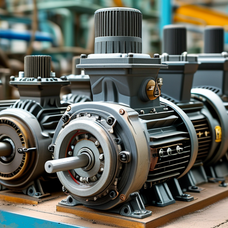
What Is an AC Drive?
What Is an AC Drive?
An AC drive is an electronic controller that regulates an alternating-current motor. It changes the power delivered to the motor, rather than simply switching it on or off. Inside, the drive converts incoming AC power into DC power. An inverter then rebuilds that power at a controlled frequency and voltage. Motor speed follows frequency, while voltage helps maintain suitable magnetic conditions and torque.
In a factory, this control can make a conveyor start gently instead of jolting its gearbox. A pump may slow down when demand falls, reducing unnecessary energy use. Fans can also avoid running at full speed all day. These effects improve process control and may reduce mechanical wear. The result depends on correct sizing, wiring, motor compatibility, and careful parameter settings.
The explanation sounds neat, but real installations are less tidy. Long motor cables can increase electrical stress and create interference. Rapid switching may also produce harmonics or unwanted bearing currents. Engineers should check the motor’s insulation, cooling method, load pattern, and stopping requirements before commissioning. In my experience, many faults begin with rushed setup rather than defective hardware. A practical installation includes proper grounding, ventilation, protection, and measured tests under real operating conditions. Safety procedures still matter.
How AC Drives Control Industrial Motor Speed
Why Use an AC Drive for Industrial Motors?
An AC drive controls motor speed by changing the frequency and voltage supplied to the motor. Lower frequency produces slower rotation. Higher frequency increases speed within safe operating limits. This method matches motor output with real process demand, instead of forcing full-speed operation through mechanical restrictions.
During practical commissioning, a drive can reduce water-pump speed during low demand. The motor then avoids unnecessary torque, heat, and electrical consumption. The U.S. Department of Energy reports that motor-driven equipment uses about 69% of industrial electricity in the United States, according to its Motor Systems Market Assessment. Even small speed reductions can matter. For centrifugal pumps and fans, affinity laws show that power may fall approximately with the cube of speed. A 20% speed reduction could therefore cut theoretical power demand by nearly half.
The numbers need caution.
Actual savings depend on load profile, motor efficiency, harmonics, and maintenance. The International Energy Agency has reported that electric motor systems consume roughly half of global electricity, making control improvements highly significant. An AC drive also supports soft starting, reducing mechanical shock on couplings and belts. However, incorrect parameter settings can create instability, overheating, or disappointing savings. Engineers should verify motor data, cooling requirements, cable length, and braking needs before installation. The drive is not an automatic efficiency solution; it is a precise control tool that rewards careful application.
Key Benefits of AC Drives in Industrial Applications
Why Use an AC Drive for Industrial Motors?
Key Benefits of AC Drives in Industrial Applications
Industrial motors often run at full speed, even when a process needs less output. An AC drive adjusts motor speed by controlling frequency and voltage. This can reduce energy use in pumps, fans, and compressors. The result is practical, not theoretical. A slower pump may also create less pressure stress in the piping.
On a conveyor, an AC drive provides controlled acceleration and deceleration. Less mechanical shock. Belts, couplings, and gearboxes may experience lower wear. Operators can set speed changes from a control panel or automation system. Built-in fault information can also reveal overloads, overheating, or stalled motors. That information supports faster troubleshooting, although it does not replace inspection.
AC drives improve process control as well. A mixer can maintain a steadier speed when material thickness changes. A fan can respond to temperature readings instead of running constantly. However, selecting a drive is not automatic. Incorrect motor data, poor ventilation, or unsuitable cable lengths can cause problems. Heat, dust, and moisture matter. So does electrical compatibility.
Proper sizing requires attention to motor current, load profile, starting torque, and braking needs. Engineers should also check harmonics and installation conditions. From field experience, commissioning often reveals small issues that specifications miss. Real gains appear when settings match the equipment. Not overnight. Regular checks of terminals, cooling paths, and fault records help maintain reliable operation.
AC Drive Energy Savings and Motor Protection
Why Use an AC Drive for Industrial Motors?
AC Drive Energy Savings and Motor Protection
An AC drive controls motor speed by adjusting frequency and voltage. This matters most in pumps, fans, and conveyor systems with changing workloads. A pump running at half speed may use far less energy than one operating fully open. The exact saving depends on load type, pipe resistance, and operating hours.
Real-world measurements should guide the decision. Record motor current, speed, running time, and process demand before installation. A drive can reduce frequent starts and limit mechanical shock through controlled acceleration. It can also detect overloads, phase loss, overvoltage, undervoltage, and stalled conditions. These functions help protect windings, couplings, belts, and gearboxes.
Protection is not automatic perfection. Low-speed operation may reduce the motor’s cooling airflow, especially with a standard fan-cooled motor. Harmonics, incorrect settings, or poor grounding can create additional problems. Technicians should check motor insulation, cable length, braking needs, and cooling performance. Sometimes, a drive is installed without reviewing the process, and the expected savings disappoint. That mistake is worth admitting. Proper commissioning, periodic inspection, and trend monitoring make the energy reduction more credible and the motor’s service life easier to manage.
Factors for Selecting an AC Drive for Industrial Motors
Why Use an AC Drive for Industrial Motors?
An AC drive can reduce energy use, control speed, and limit mechanical stress during starting. Selection begins with the motor’s real operating profile, not its nameplate alone. Check rated voltage, full-load current, torque demand, acceleration time, and daily duty cycle. A conveyor needs different control behavior from a centrifugal pump. Oversizing seems safe, but it can reduce control accuracy and increase purchase costs.
The International Energy Agency reports that electric motor-driven systems consume roughly 43–46% of global electricity. The U.S. Department of Energy also identifies motor systems as responsible for more than 70% of industrial electricity use in many facilities. These figures make efficiency important, but efficiency claims need operating evidence. Compare expected savings across actual load points, not only at full speed. Variable-torque loads may deliver strong savings, while constant-torque machines demand careful overload sizing.
Environmental conditions matter. Dust, humidity, heat, altitude, and washdown routines can shorten drive life without suitable enclosure protection. Evaluate harmonic distortion, electromagnetic compatibility, braking requirements, and emergency-stop integration. Confirm whether the drive supports the motor’s overload rating and required low-speed torque. Maintenance teams should review display clarity, fault history, spare availability, and communication protocols. A highly capable drive may still fail operationally if technicians cannot troubleshoot it quickly. That is an uncomfortable detail. Energy models can also be optimistic when production schedules change. Use measured load data where possible, then validate performance after installation against standards such as IEC 61800 and applicable plant requirements.
Why Use an AC Drive for Industrial Motors? - Factors for Selecting an AC Drive for Industrial Motors
| Selection Factor | Why an AC Drive Is Used | Typical Data or Requirement | Selection Guidance |
|---|---|---|---|
| Process Speed Control | Provides adjustable motor speed without mechanical throttling or frequent manual intervention. | Output frequency is commonly adjustable from 0 Hz to the motor's rated frequency, often 50 or 60 Hz. | Select a drive with a frequency range and speed accuracy suitable for the process. Confirm the motor's allowable minimum speed and cooling requirements. |
| Motor Compatibility | Controls the voltage and frequency supplied to the motor to support controlled starting, stopping, and operation. | Common applications use three-phase induction motors; permanent-magnet and synchronous reluctance motors require compatible control modes. | Match the drive control method to the motor type. Verify rated voltage, rated current, base frequency, insulation system, and motor feedback requirements. |
| Voltage and Supply | Converts incoming electrical power into controlled output power for the motor. | Industrial supplies commonly include 200–240 V, 380–415 V, 460–480 V, or 575–600 V three-phase systems, depending on the installation. | Choose the drive input and output voltage class based on the measured supply and the motor nameplate. Account for allowable voltage variation and phase configuration. |
| Motor Rated Current | Current-based sizing helps the drive deliver the required torque and prevents thermal overloading. | The motor nameplate full-load current is more important for sizing than horsepower or kilowatt rating alone. | Select a drive whose continuous output current is at least equal to the motor's rated current under the actual overload and ambient conditions. |
| Load Type and Torque | Provides torque control appropriate for pumps, fans, conveyors, mixers, compressors, and other industrial loads. | Variable-torque loads generally require less starting torque than constant-torque or high-inertia loads. | Use a variable-torque rating for centrifugal pumps and fans when applicable. Use a constant-torque or heavy-duty rating for conveyors, crushers, mixers, and high-inertia equipment. |
| Overload Capacity | Allows the motor and drive system to handle temporary increases in load without unnecessary trips. | Many industrial drives provide approximately 110% to 150% of rated current for a limited time, depending on the duty class. | Compare the required acceleration torque, peak load, duration, and repetition rate with the drive's published overload profile. |
| Energy Efficiency | Reduces motor speed when full output is not required, especially in variable-torque applications. | For centrifugal fans and pumps, affinity laws indicate that flow is proportional to speed, pressure is approximately proportional to speed squared, and power is approximately proportional to speed cubed. | Estimate savings from the actual operating profile, static head, minimum flow, duty cycle, drive losses, and motor efficiency rather than speed reduction alone. |
| Starting Current and Mechanical Stress | Ramps motor acceleration and limits inrush current compared with direct-on-line starting. | Direct-on-line induction motor starting current can commonly be several times the motor's rated current. | Select adjustable acceleration and deceleration times based on load inertia, process limits, and the available electrical supply. |
| Braking and Stopping | Provides controlled deceleration and can manage regenerative energy from overhauling or high-inertia loads. | Stopping methods may include ramp-to-stop, DC injection, dynamic braking, or regenerative braking. | Use a braking resistor for suitable intermittent braking duty. Consider a regenerative solution when braking energy is frequent or substantial. |
| Control Performance | Supports open-loop or closed-loop control for improved speed, torque, and process regulation. | Scalar control is often adequate for basic applications; sensorless vector or closed-loop vector control is used when higher torque or speed control is needed. | Select the control mode according to low-speed torque, speed accuracy, dynamic response, positioning, and feedback requirements. |
| Operating Environment | Protects the drive from heat, dust, moisture, vibration, and corrosive conditions that can affect service life. | Common enclosure ratings include IP20 for protected control cabinets and higher ratings for equipment installed in exposed areas. | Check ambient temperature, altitude, humidity, dust, chemicals, vibration, cooling clearance, and required enclosure rating. Apply derating where required. |
| Harmonics and Power Quality | Power-electronic rectifiers can introduce current harmonics into the supply system. | Harmonic impact depends on drive topology, system impedance, number of drives, transformer size, and operating load. | Evaluate the installation against applicable power-quality limits. Consider line reactors, passive filters, active filters, or low-harmonic configurations when necessary. |
| Motor Cable and Insulation | High-frequency switching produces voltage pulses that can affect long motor cables, bearings, and motor insulation. | Risk increases with long cable runs, high carrier frequency, poor grounding, and motors not designed for inverter operation. | Follow drive and motor cable limits. Use shielded symmetrical cable, proper grounding, output reactors, or sine-wave filters where the installation requires them. |
| Communication and Automation | Enables remote commands, speed references, status monitoring, diagnostics, and integration with industrial control systems. | Typical interfaces include digital inputs and outputs, analog signals, serial communication, and industrial Ethernet protocols. | Confirm required data points, response time, network architecture, cybersecurity controls, and compatibility with the plant control system. |
| Safety Functions | Can support controlled safety-related stopping without removing power from the entire installation. | A commonly used function is Safe Torque Off, which prevents the drive from producing motor torque when correctly implemented. | Define the required safety category or performance level through a formal risk assessment and verify the complete safety circuit, not only the drive function. |
| Reliability and Maintenance | Provides fault monitoring, protective trips, operating data, and adjustable parameters that can simplify troubleshooting. | Important maintenance items include cooling fans, filters, terminals, DC-link capacitors, and cabinet ventilation. | Review service intervals, spare-part availability, fault history, thermal loading, and the required environment before final selection. |
| Standards and Compliance | Helps ensure the drive and installation meet electrical, EMC, safety, and machinery requirements. | Common references include IEC 61800 series requirements for adjustable-speed electrical power drive systems and applicable local electrical codes. | Confirm the required regional approvals, EMC installation practices, short-circuit rating, grounding method, and documentation before purchase. |
Related Posts
-
Understanding AC Drives: The Key to Energy Efficiency in Modern Industrial Applications
-
Top 10 Benefits of Using an AC Drive in Industry?
-
What is a Frequency Drive and How Does It Work?
-
What is a Frequency Drive and How Does it Work?
-
Top 10 Frequency Drive Suppliers in China for Global Buyers?
-

Top 10 Benefits of Variable Speed Drive Motors for Buyers