

What Is an Inverter IGBT Welder and How Does It Work?
An Inverter Igbt Welder uses electronic switching to convert incoming electrical power into a controlled welding current. Unlike a traditional transformer welder, it typically relies on insulated-gate bipolar transistors, or IGBTs, to switch power rapidly. The result is a compact machine with adjustable output for processes such as stick and TIG welding, depending on the model. Small case, serious work.
Inside, the machine first rectifies incoming AC power into DC. Its inverter circuit then switches that power at high frequency, and a transformer adjusts the voltage before the output is controlled for welding. This sequence helps explain why many inverter welders are lighter than older transformer-based units. It also gives operators fine control over settings such as current, which matters when working with different electrode sizes or material thicknesses. The arc should feel steady, but settings and technique still matter.
A welder’s label alone does not tell the whole story. Duty cycle, input-power requirements, cooling, and the quality of the leads can affect real performance. For example, a machine rated for high output may need a suitable supply and cooling breaks during extended work. Manufacturer specifications are worth checking before purchase or use. One detail is easy to miss: a stable arc cannot correct poor preparation, a dirty joint, or an unsuitable setting. Understanding how an Inverter Igbt Welder works can help users choose equipment more carefully and troubleshoot common issues, though hands-on practice remains essential. Even experienced users sometimes need to reassess their settings.
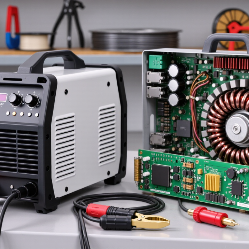
What an Inverter IGBT Welder Is
An inverter IGBT welder is an arc-welding power source. It uses inverter electronics and insulated-gate bipolar transistors, or IGBTs, to regulate welding current. Inside the unit, incoming power is converted and switched at high frequency, then adjusted to provide a controlled welding output. This differs from older designs that depend on larger, low-frequency transformers. The result is often a lighter machine that is easier to move between a bench and a job site. Compact, but not simple.
The IGBTs act as fast electronic switches. Their switching helps control how much power reaches the welding arc, while the machine’s control circuit adjusts output to suit the selected settings. For example, a welder may provide a steadier current for joining steel parts with a stick electrode. The case may be small, yet it still needs clear airflow; dust and blocked vents can contribute to overheating. Internal design varies, so the label alone does not tell you every feature.
“IGBT” describes a key component, not a welding process or a guarantee of performance. Duty cycle, input voltage, current range, and electrode compatibility matter when choosing a unit. A display can show a current setting, but actual arc behavior also depends on technique, material, and electrode condition. That part is easy to underestimate. Even a capable inverter welder can feel harsh or unstable when settings are poorly matched.
What Is an Inverter IGBT Welder and How Does It Work? - What an Inverter IGBT Welder Is
| Aspect | What It Is or Does | How It Works in the Welder |
|---|---|---|
| Inverter IGBT welder | An arc-welding power source that uses an inverter circuit with insulated-gate bipolar transistors (IGBTs) to control electrical power. | It converts incoming electrical power into a controlled welding output. The inverter switches power at high frequency, allowing the machine to use a smaller transformer than a traditional line-frequency design. |
| Input rectifier | A circuit that converts incoming alternating current (AC) into direct current (DC). | Rectifier components turn the input AC into DC for the inverter stage. The exact input voltage and phase depend on the welder model and its rated supply. |
| IGBT switching stage | A set of electronic switches that rapidly turns electrical power on and off. | The control circuit drives the IGBTs in a switching pattern. Pulse-width modulation is commonly used to regulate the power delivered to the welding circuit. |
| High-frequency transformer | A transformer that changes voltage and current levels while providing electrical isolation in many designs. | It receives the inverter’s switched, high-frequency power and transforms it to a voltage suitable for the machine’s welding-output stage. High-frequency operation enables a more compact transformer than a traditional mains-frequency transformer. |
| Output rectifier and filtering | Components that convert the transformer output into the required welding current and help smooth it. | In many DC-output welders, output rectifiers convert the transformed waveform into DC. Filtering components reduce unwanted ripple before power reaches the welding terminals. |
| Control and feedback | Electronic circuits that monitor operating conditions and regulate the welding output. | Feedback from the output helps the control circuit adjust switching to maintain the selected current as welding conditions change, within the machine’s rated operating limits. |
| Welding output | The current and voltage supplied between the electrode and the workpiece to establish and maintain an arc. | The operator selects settings supported by the machine. The resulting arc melts the electrode and/or base metal, depending on the welding process and consumables used. |
| Common processes | Many inverter power sources are designed for processes such as stick (MMA/SMAW), TIG (GTAW), or MIG/MAG (GMAW), depending on the model. | Process capability depends on the machine’s output characteristics, controls, accessories, and rated duty cycle; not every inverter IGBT welder supports every process. |
| Typical advantages | Compact size, lower weight than many conventional transformer-based units, and electronic output control. | High-frequency switching makes smaller magnetic components practical. Actual efficiency, portability, and performance vary by design, input supply, settings, and operating conditions. |
| Operating considerations | Input-power requirements, ventilation, duty cycle, and correct polarity or process setup. | Use a supply and protective equipment that meet the welder’s rating. Keep cooling passages clear, observe the specified duty cycle, and follow the operating manual and applicable safety practices. |